The laser interferometer satellite antenna (LISA) has been prepared as a joint (if financially delayed) experiment between the National Aeronautics and Space Administration (NASA) and the European Space Agency (ESA).
A BBC Horizon televisation of a decade or two ago suggested that string theory might have to rely on mathematics to discover the theory of everything, because the prospects of it being tested were so remote.
Reading Brian Greene, it would appear that experiment is essential to narrow
down the almost limitless variety of possible hyper-spatial (or at any rate
geometrical) solutions to find those which apply to reality.
Reading a book like Gravitys Engines, by the astronomer Caleb Scharf, it seems
that revolution in physical theory is fast being caught, if not overtaken, by
ever more fantasticly accurate technology.
LISA is just such an experiment.
Scientific qualifications, like general relativity, are needed to understand
it. Enormous technical difficulties are being over-come to implement it. So,
this member of the public, feels that I have a nerve to discuss it at all.
The purpose of this page is a continuation of my amateur investigations into the Michelson-Morley experiment, because LISA is a descendant of that test.
Years ago, I noticed that the Michelson-Morley calculation didn't agree with experiment because it used the arithmetic mean, instead of the geometric mean, to arrive at averages for the respective longitudinal and transverse beam reflections.
The notice taken of my realisation was minimal. This was a blessing in disguise, because it allowed my thoughts on the subject to go wandering on. I did a page to show that geometric averaging for the M-M calculation is consistent with the Minkowski Interval. Another page showed that the arithmetic mean calculation does not provide solutions in terms of the Lorentz transformations.
I regarded the Fitzgerald-Lorentz contraction as an ad hoc hypothesis,
smuggling geometric averaging into the calculation. More recently, I suggested
that the M-M experiment be better seen in terms of satisfying the Least Action
principle.
I also had the feeling that this great experiment might have something to say
about a new conservation law, perhaps momentum change, given that there is a
relative change in velocity both longitudinally and transversely.
By Noether theorem, conservation laws have corresponding symmetry operations. I was not looking for a new conservation law. What happened was that I had been thinking of mathematics having to be self-representational, just as the universe by definition must be self-contained, by a sort of Mach principle of consistency. Thus, complex numbers could represent each other as averages of range limits.
Moreover, the Minkowski Interval, of special relativity, as an example of a
circular function, leant itself to such statistical treatment of complex
numbers.
The Interval, and a variation on it, in statistical terms, were reminiscent of
a wave equation and damped wave equation, but gave the same answer regardless.
(It's on my page about amplitude symmetry.) It is the amplitude of the wave
which is damped.
In other words, there appeared to be symmetry of amplitude. If this was a new symmetry operation, it had to have a corresponding new conservation law.
The Michelson-Morley experiment does seem to lend itself to conservation in terms of beam reflections changing relative velocity (or, conceivably, momentum, which is mass times velocity).
In the M-M laboratory experiment, the transverse beam is at right angles to the longitudinal beam.
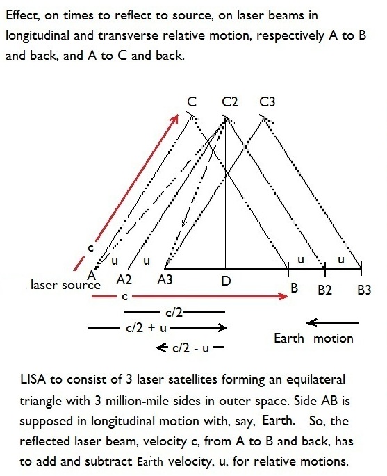
In the proposed cosmic scale LISA experiment, the laser beams are not at right angles to each other. They are mounted on three identical satellites at 60° to each other. Each side of the triangle is five million kilometres long. If one side of the triangle moves longitudinally in relation to a reference point, such as the Earth or its center, then one of the other sides (relatively) moves transversely.
None of this discussion is meant to describe the projected LISA experiments, which I'm not remotely qualified to do. For the sake of argument, Ive assumed that the motion of a reference point, such as the Earth is measured relative to its orbit of the Sun. But this particular isn't essential to the following discussion.
Unlike the Michelson-Morley experiment, LISA could not use mirror reflections, which would be too faint to return over millions of kilometres. Nor are the beams split, for this purpose. Instead, when a beam travels from one satellite to the other, it triggers a return beam. I have assumed that this is, in effect, a reflection, that does not affect the argument.
The LISA amplitude of the 60° transverse motion is less than the maximum amplitude of a 90° transverse motion found in the M-M experiment. I have already done my calculation for maximum amplitude. (See my page: The Michelson-Morley null result as a linear-angular momentum change conservation.) Now I will repeat my workings for a lesser amplitude experimental set-up, namely the LISA project.
The explanation will be guided by my LISA diagram below. It compares to the diagram, on the above-referenced page. The LISA diagram shows three successive triangle positions.
 In the M-M diagram, I could have drawn three successive perpendicular positions
of the transverse mirror but I only drew the vertical mid-position, when the
transverse beam reaches its reflection from and back to the source. The M-M
diagram shows the transverse beam, at light speed, c, being shifted the same
angle before and after its reflection, with respect to the same Earth velocity,
u. This forms two symmetrical triangles about the vertical mid-position.
In the M-M diagram, I could have drawn three successive perpendicular positions
of the transverse mirror but I only drew the vertical mid-position, when the
transverse beam reaches its reflection from and back to the source. The M-M
diagram shows the transverse beam, at light speed, c, being shifted the same
angle before and after its reflection, with respect to the same Earth velocity,
u. This forms two symmetrical triangles about the vertical mid-position.
By Pythagoras theorem, both triangles derive the same magnitude for this vertical, tho their vector arrows are in opposite directions.
In the LISA diagram, the procedure is very like, tho appearances are somewhat different, because the transverse beam no longer forms a symmetrical reflection, when aimed at 60°, instead of 90°, to the longitudinal beam. The dashed lines show this asymmetry, with the reflected line being shorter than the out-going line and creating a lop-sided appearance, unlike the tent-shaped symmetry of the M-M diagram.
Nevertheless, the asymmetrical dashed lines, of the out-going transverse beam and its reflection, share the same magnitude vertical vector component to their otherwise different sized triangles.
The fact that Pythagoras theorem is being used assumes Euclid geometry of flat space, and, by extension, the Minkowski geometry of a flat space-time. On average, outer space geometry is that of a flat space-time, which will be the environment that LISA is launched into.
It is true that the purpose of LISA is to detect incredibly small ripples in this flat fabric of space and time, such as would leave a measurable difference in the lengths of the sides of the satellite triangle. These ripples would be gravitational waves, predicted by general relativity to result from colossal disturbances, notably emanating from far-away but massive black hole collisions, and a host of other disruptive astrophysical phenomena, outlined on the NASA page: LISA Project Office.
However, for my modest purposes, it is sufficient to note that, in such cases, the Minkowski Interval, of special relativity, would momentarily not hold.
So, assuming the normal condition of space-time flatness, I calculate the Minkowski Interval for a LISA type triangle, shown in the diagram, with two laser beams, one bouncing forth and back, from the corner, marked, A, in the longitudinal direction to the corner, B, and the other beam from corner A to the transverse corner, marked C.
The calculation for the longitudinal relative velocity of the beam, with some reference point, such as Earth motion, is easy. Longitudinally, the LISA case is the same as the M-M case.
However, I am using the geometric mean to average the forth and back
longitudinal relative velocities.
This contradicts well over a century of following the authority of the
Michelson-Morley calculation, which uses the arithmetic mean.
Not surprisingly, the physics community has not been eager to suspend belief in themselves, even on this particular point, to go along instead with the view of one relatively ignorant and easily confused layman.
Nevertheless, my heretical geometric averaging of the M-M calculation is consistent with the Minkowski Interval formula.
As in the diagram, say the longitudinal beam starts off in the same
direction as the body, Earth, it is moving relative to. Then it will take
longer, by that bodys motion, (that is, speed: c - u), to reach its reflection
point.
But on reflection, returning to its source, the beam will be moving in opposite
direction to that body, which means, relatively speaking, it takes on the
combined velocity, (c + u), of its own light speed, c, and the reference bodys
speed, u.
Now, a reflection implies a change in velocity, relative to the reference body motion. That means relative acceleration, for which the suitable average is the geometric mean.
For example, the suitable average to measure a range of simple interest over time, is the arithmetic mean: the addition to capital is a constant increase. But to measure the average interest, for a given growth of capital by compound interest, requires the geometric mean. Compound interest accelerates the increase in capital, with the interest taken on a capital including previous interest added to it.
The geometric mean of the longitudinal beam journey is the square root of
the multiple of the out-going and return journeys: {(c+u)(c-u)}^1/2 = (c² -
u²)^1/2.
This equals the velocity measurement for the transverse beam and so gives the
correct prediction for the Michelson-Morley experiment. The same velocities
over the same distances imply the same time for the light beams to return to
source, as is what happens.
But this is also the form of the velocity part of the Minkowski Interval for any local observer of a given event, significantly approaching light speed dimensions.
The Minkowski Interval, I, might be given as:
I² = t²(c² - u²) = T²(c² - U²).
The Interval is a constant common to all local observers of some event. It has dimensions of distance, being equal to a multiple of time, t or T, by velocity, u or U. The upper and lower case letters merely mean that different local observers measure different local times and velocities. But they all agree on a common so-called spacetime measurement of the event, called the Interval.
The lower case observation is satisfied by the longitudinal relative motion of either the M-M experiment or LISA project.
The Minkowski Interval can be satisfied for the Michelson-Morley experiment by making the times of the two observations, longitudinal and transverse, the same. Whilst converting the transverse beam journey, into imaginary velocities, signifies ninety degrees turn of the reference body to the transverse beam.
In algebraic terms, the Minkowski version of Michelson-Morley could be rendered:
I² = t²(c² - u²) = t²(c² + [iu]²).
As the longitudinal relative motion is the same for LISA as for M-M, all that needs to be done is find its transverse form. Because the longitudinal case is in one dimension, it was possible to take an average of that dimension. But the transverse case is in two dimensions.
As in the M-M diagram, the LISA diagram shares a vertical vector component. In the latter case, it is (C2.D) to the triangles made by the out-going and reflected transverse beams.
By Pythagoras, this is the square of the hypotenuse, (A2.C2) of velocity c, subtracted from the square of (A2.D) of velocity c/2.
That is (C2.D)² = c² - (c/2)² = 3c²/4.
This already gives, velocity-wise, the LISA transverse part of its Minkowski Interval, letting U² = [c/2]². Equating that to the longitudinal part, the LISA form of the Minkowski Interval is:
I² = t²(c² - u²) = T²(c² - [c/2]²).
In the diagram, velocity U = c/2 is on the same baseline as velocity, u.
That is, they are on the same (Euclid) dimension.
In the lower case part, longitudinal beam velocity, c, is also on this same
dimension. That is to say, the longitudinal beam journey is confined to a
single dimension, as the term implies.
Transverse motion implies a second dimension, at variance with the longitudinal baseline. This second dimension is found in the sixty degrees transverse beam. The square of this beams light speed is given in the transverse (upper case) part of the LISA Interval, which is therefore appropriately expressed in two dimensions.
It will be seen that this LISA Minkowski Interval, unlike the M-M Interval, shows the longitudinal and transverse beams generally taking different times to go forth and back, in order that they measure the same Interval, I.
That is: T²/t² = 4(c² - u²)/3c².
Or:
T/t = 2{(1 - u²/c²)/3}^1/2.
If the longitudinal and transverse beams do not share the same value for the Interval, I, by ever so small an amount, astronomers would no doubt search for some candidates for the violent cosmic upheaval that apparently caused local distortions in the lengths of spacetime covered by the Laser Interferometer Satellite Antenna.
Disclaimer:
My web pages have not been independently checked, tho I corrected such
mistakes as I found.
There may be some wheat amongst all the chaf.
Richard Lung.
15 november 2013.